 SS4544
SyncroStep
Motion Control System
1.0 POWER INPUT CONNECTION
1.1 POWER CONNECTOR
1.2 FUSING
1.3 POWER CORD
2.0 RS-232 INTERFACE
2.1 RS-232 CONNECTOR
2.2 RS-232 CORD SET
2.3 DB-9F ADAPTOR
2.4 DB-25F ADAPTOR
3.0 RS-485 INTERFACE
3.1 RS-485 CONNECTORS
3.2 RS-485 CORD SET
4.0 INTERLOCK
5.0 LASER/PWM
6.0 AXIS ENCODER/LIMIT
7.0 TRAINING
8.0 MOTOR CONNECTORS
9.0 MOUNTING
The SS4544 system power input connection is via a
world standard power
connector with availability of a wide range of cord sets for various
country
standards.
The input power connector is a Euro Standard 3 prong
male plug. The
connector used is:
Schurter GSF1.1101.01
It mates with many different standard power cord
sets. Cord sets should
be rated for at least 5 amps.
The input power line fuse holder is integrated with
the power inlet
connector, and is mounted inside the case. Under normal circumstances
this
fuse should not have to be replaced. The fuse being blown usually
represents some catastrophic event, meaning the unit should be returned
for
servicing. If power has been applied, and the power light does not
come on,
the fuse is probably blown.
If the fuse is replaced, and blows again, the unit
should be definitely
returned for service.
The standard fuse is a 5x20mm 3.15amp 250v Fast Blow.
Digikey WK1124-ND
The system uses a world standard cord set, depending
on the country of
use. Several standard cord sets are listed below:
The RS-232 interface is used to communicate with
a PC or other computer.
The interface connector is on the bottom end plate of the box above
the fan.
For the RS-232 interface, an 8 pin RJ-45 Modular
connector is used. The
connector in the system is as follows:
MOLEX 95001-2881
Pinouts for the connector are as follows:
1 = +5V (+5v User Power)
2 = RTSA (Request to Send)
3 = GND (Ground)
4 = TXDA (Transmitter Data)
5 = RXDA (Receive Data)
6 = GND (Ground)
7 = CTSA (Clear to Send)
8 = n/c
The cord set uses standard 8 pin modular insulation
displacement
connectors with standard 8 conductor flat jacked, color coded wire.
The
connectors are crimped so that the cable is crossing. The following
table
shows the resulting wire list for the cable:
P1
P2
==
==
1 = +5V (+5v User Power)
= 8
2 = RTSA (Request to Send)
= 7
3 = GND (Ground)
= 6
4 = TXDA (Transmitter Data) =
5
5 = RXDA (Receive Data)
= 4
6 = GND (Ground)
= 3
7 = CTSA (Clear to Send)
= 2
8 = n/c
= 1
The materials are as follows:
P1,P2 RJ-45 Plug
Wire 8 Conductor Flat Jacketed
TOOL Crimping Tool
For connection to a personal computer (PC) you will
need an adaptor going
from the 8 pin RJ-45 connector to the 9 pin DB-9 female connector.
A standard
adaptor is available to accomplish this. It needs to be wired as follows:
RJ-45
Color DB-9
=====
===== ====
1 = n/c
BLU 1
2 = RTSA (Request to Send) ORN
7
3 = GND
(Ground) BLK n/c
4 = TXDA (Transmitter Data) RED
3
5 = RXDA (Receive
Data) GRN 2
6 = GND
(Ground) YEL 5
7 = CTSA
(Clear to Send) BRN
8
8 = n/c
GRY 4
Adaptor Kit Part Number -
Testra Part Number -
For connection to a personal computer (PC) you will
need an adaptor going
from the 8 pin RJ-45 connector to the 25 pin DB-25 female connector.
A standard
adaptor is available to accomplish this. It needs to be wired as follows:
RJ-45
Color DB-25
=====
===== ====
1 = n/c
BLU 8
2 = RTSA (Request to Send)
ORN 4
3 = GND (Ground)
BLK 1
4 = TXDA (Transmitter Data) RED
2
5 = RXDA (Receive Data)
GRN 3
6 = GND (Ground)
YEL 7
7 = CTSA (Clear to Send)
BRN 5
8 = n/c
GRY 20
Adaptor Kit Part Number -
Testra Part Number -
The RS-485 interface is used to communicate with
one or more SS-xxxx
series motion control system, keyboard/display panel, sensor inputs,
and
control outputs. These connections are made in a daisy chain manner.
The
interface connectors are on the bottom end plate of the box above the
fan.
For the RS-485 interface, an 4 pin RJ-15 Modular
connectors are used. The
connectors in the system are as follows:
MOLEX 95001-2441
Pinouts for the connectors are as follows:
RS-485 INPUT
============
1 = TXRA (Transmit/Receive Ph A)
2 = TXRB (Transmit/Receive Ph B)
3 = n/c
4 = GND (Ground)
RS-485 OUTPUT
=============
1 = TXRA (Transmit/Receive Ph A)
2 = TXRB (Transmit/Receive Ph B)
3 = +5V (+5V user power)
4 = GND (Ground)
The cord set uses standard 4 pin modular insulation
displacement
connectors with standard 4 conductor (2 pair twisted) jacketed, color
coded
wire. The connectors are crimped so that the cable is non-crossing.
The
following table shows the resulting wire list for the cable:
P1
P2
==
==
1 = TXRA = 1
2 = TXRB = 2
3 = +5V = 3
4 = GND = 4
The materials are as follows:
P1,P2 RJ-15 Plug
Wire 4 Conductor Flat Jacketed
TOOL Crimping Tool
The interlock connector is used for the termination
of a safety daisy
chain. This is a two pin MOLEX C-Grid SL connector located at the bottom
edge of the top panel. The two pins must be connected together to allow
operation (if programmed in the application). If the connection is
broken,
the motors and laser drive can be shut down. The connector in the system
is
a MOLEX 70545-0036 which is wired as follows:
PIN FUNCTION
=== ========
1 GROUND
2 INTERLOCK
The mating connector parts listed as follows:
SHELL - MOLEX 50-57-9402
PINS - MOLEX 16-02-1116 (70058
series)
CRIMPER - MOLEX 11-01-0209
WIRE - 24-28 AWG STRANDED
An alternative is the Insulation Displacement Connector Assembly
CONNECTOR - MOLEX 14-56-2022 (70400 series)
DISCRETE WIRE TERMINATOR HANDGUN
HANDLE - MOLEX 11-21-5194
CRIMP MODULE- MOLEX 11-32-5759
Semi-automatic and automatic assembly equipment is available from Molex for use with ribbon cable for high volume applications.
CABLE - MOLEX (7307 series) 82-28-58028 or (24369 series - High Flex) 82-26-6202
The LASER/PWM connector is used to output a pwm pulse
train for
modulating a laser beam, or controlling a spindle motor. This is a
three pin
connector located near the bottom edge of the top panel. The connector
in
the system is a standard MOLEX C-Grid SL (70545-0037) which is wired
as
follows:
PIN FUNCTION
=== ========
1 PWM
2 GROUND
3 SENSE
The mating connector parts listed as follows:
SHELL - MOLEX 50-57-9403
PINS - MOLEX 16-02-1116 (70058
series)
CRIMPER - MOLEX 11-01-0209
WIRE - 24-28 AWG STRANDED
An alternative is the Insulation Displacement Connector Assembly
CONNECTOR - MOLEX 14-56-2032 (70400 series)
DISCRETE WIRE TERMINATOR HANDGUN
HANDLE - MOLEX 11-21-5194
CRIMP MODULE- MOLEX 11-32-5759
Semi-automatic and automatic assembly equipment is available from Molex for use with ribbon cable for high volume applications.
CABLE - MOLEX (7307 series) 82-28-5803 or (24369 series - High Flex) 82-26-6203
For descrete wiring, it is recommended that the cable
made up for this connector be shielded,
with the shield connected to ground on the connector. Flat cables
should be kept away from noise sources, such as the motor leads which should
be shielded by themselves.
There are four axis encoder/limit connectors, each
associated with
one of the four motor axes. The connectors in the system are standard
MOLEX
6 pin C-Grid (70545-0040) which are wired as follows:
PIN FUNCTION
=== =================
1 +5V
2 LIMIT
3 INDEX
4 GND
5 ENCODER-Phase A
6 ENCODER-Phase B
The mating connectors with latches to prevent accidental
extraction and
associated parts listed as follows:
SHELL - MOLEX 50-57-9406
PINS - MOLEX 16-02-1116 (70058
series)
CRIMPER - MOLEX 11-01-0209
WIRE - 24-28 AWG STRANDED
An alternative is the Insulation Displacement Connector Assembly
CONNECTOR - MOLEX 14-56-2062 (70400 series)
DISCRETE WIRE TERMINATOR HANDGUN
HANDLE - MOLEX 11-21-5194
CRIMP MODULE- MOLEX 11-32-5759
Semi-automatic and automatic assembly equipment is available from Molex for use with ribbon cable for high volume applications.
CABLE - MOLEX (7307 series) 82-28-5806 or (24369 series - High Flex) 82-26-6206
For descrete wiring, it is recommended that the cable
made up for this connector be shielded,
with the shield connected to ground on the connector. Flat cables
should be kept away from noise sources, such as the motor leads which should
be shielded by themselves.
There is one 8 pin training connector. The connector
in the system is a
standard MOLEX C-Grid SL (70545-0042) which is wired as follows:
PIN FUNCTION
=== =================
1 +5V
2 ENCODER-Y Phase
B
3 ENCODER-Y Phase
A
4 GND
5 ENCODER-X Phase
B
6 ENCODER-X Phase
A
7 INDEX-Y
8 INDEX-X
The mating connector parts listed as follows:
SHELL - MOLEX 50-57-9408
PINS - MOLEX 16-02-1116 (70058
series)
CRIMPER - MOLEX 11-01-0209
WIRE - 24-28 AWG STRANDED
An alternative is the Insulation Displacement Connector Assembly
CONNECTOR - MOLEX 14-56-2082 (70400 series)
DISCRETE WIRE TERMINATOR HANDGUN
HANDLE - MOLEX 11-21-5194
CRIMP MODULE- MOLEX 11-32-5759
Semi-automatic and automatic assembly equipment is available from Molex for use with ribbon cable for high volume applications.
CABLE - MOLEX (7307 series) 82-28-5808 or (24369 series - High Flex) 82-26-6208
For descrete wiring, it is recommended that the cable
made up for this connector be shielded,
with the shield connected to ground on the connector. Flat cables
should be kept away from noise sources, such as the motor leads which should
be shielded by themselves.
There are four axis motor connectors. The connectors
in the system are
five pin PHOENIX CONTACT 17 55 76 5 which are wired as follows:
PIN UNCTION
=== ========
1 GROUND
SHIELD
2 Motor
Phase B-
3 Motor
Phase B+
4 Motor
Phase A-
5 Motor
Phase A+
NOTE: Pin one is on the left with the scallops at
the back. They
number left to right when your are looking at an edge of the box.
The mating connector with screw terminals and latches
to help prevent
accidental extraction is:
PHOENIX CONTACT 17 57 04 8
In making up a cable for the motor, the four motor
wires should be
shielded, and the shield should be connected to the ground (pin 1)
and be
grounded to the motor case. No other wires should be inside the shield.
The SS-4445 System was designed to mount vertically,
with the power
connection at the top of the box, and the communications connections
at the
bottom of the box. This will give optimum cooling, allowing convection
to
move air vertically over the heat sinks. There is also an internal
fan that
moves air from the bottom of the box over the motion control board,
and
exits out the top from the power supply section.
Any other mounting orientation is also OK, but additional
consideration
will have to be given to surrounding air flow, and how much power will
be
disapated in the particular application.
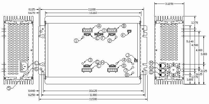
The system requires a mounting space of approximately
8x12 inches with
a thickness of about 4 inches. This allows space for cables. The standard
mounting tabs protrude from the end plates and have two sets of mounting
holes. One set is set up for mounting to a standard 1 inch grid 1/4-20
machine plate. The other set is set up for #8 pan head phillips head
clearance slots.
GO TO HOME PAGE
If you have comments or suggestions, email us
at support@testra.com
Testra Corporation 1201 N. Stadem Drive Tempe, AZ
85281 Ph. 480-560-6141 Fax: 480-907-2876
This page created with Netscape Navigator Gold