 SS4544
SyncroStep*
Motion Control System
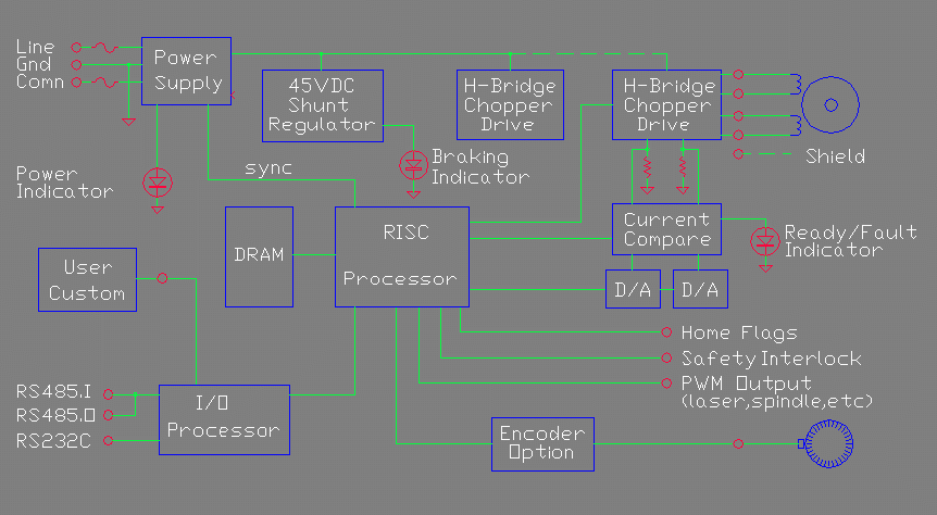
The SS Series are integrated motion systems that may be used standalone, as a slave to another acting as a master, a slave to a PC or as a component of a large system. Figure 1 shows a system block diagram with one of the possible axes..
The Model SS4544 is suitable for driving four stepper motors up to a 34 size, with bipolar H-Bridge current drive up to +/- 5.0 amps, and +/- 44 volt compliance. Winding current is controlled with 8 bit D/A converters, with a patented method we call Synchro-Stepping*, resulting in micro-step positioning control as small as 1/256th of a step. Winding currents are synchronously adjusted in all controlled windings every 20 microseconds, either adding or subtracting current to keep it in its desired state. The winding is then put back in the re-circulating mode. Current may be sourced or sunk, for dynamic braking.
The motion profile is controlled by a 25 mips 16 bit RISC processor which is implemented within the same EPLD chip that controls the winding currents. Logic is flash based with in circuit programmability. A second processor, an 8 bit 8051 type, running at 8 mips, serves as the boot loader, and communications processor, which services the RS-485 multidrop link, and RS-232 port.
The RISC processor has a 128K byte 12 ns memory for storage of the control programs, and up to 32 megabyte of optional DRAM memory. This DRAM memory is available for the more sophisticated applications. A few of the uses are as follows: 1. May be used for storage of motion programs which include mixed vector and raster graphics, for example engraving.. 2. Motor pole compensation mapping of a linear motor for micron accuracy over a very large area, for example using a laser interferometer to map all of the motor poles. 3. Capturing motor performance data for automatic tuning. .

The I/O processor has 128K bytes of Flash EPROM which contains the control programs and operating system. It also contains 32K bytes of RAM. An additional 128K bytes of non volatile memory is available for storage of application constants, and field updates.
A user slot and connection to the processor and power is available for custom interfaces that cannot be handled by the standard hardware set. This allows a complete turnkey system to be implemented within the unit. An example of an interface that could be installed is a CAN bus or an ETHERNET controller.
Input power requirements are 85-285VAC 50-60 HZ. The standard power converter uses an auto switcher to convert to an internal 240-400VDC raw supply which is then converted with an isolated flyback switching regulator to the internal system voltages. The switching regulator is synchronized with the motor drive chop rate to eliminate noise coupling.

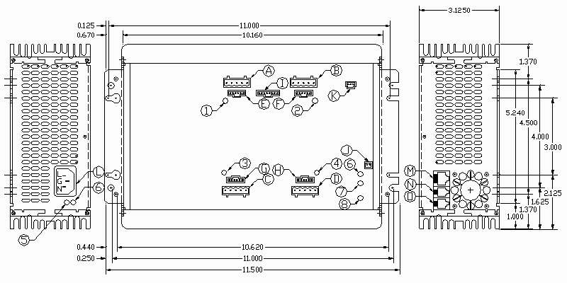
Figure 2. Mechanical Layout of the SS4544 System
Indicators
There are nine indicators on the system, electronic axis fuses, power, brake, and communications status.
Axis Fuse (1-4) - These green LEDs are lit whenever a corresponding axis is enabled and power is being applied to an axis motor. If a fault condition occurs, the light will go out. Electronic sensing protects against any kinds of shorts in the motor circuitry.
Power (5) - This green LED is lit whenever system power is running. It is located next to the input power plug.
Brake (6) - This red LED is lit whenever power is being absorbed by the system due to dynamic braking, i.e. the motors are acting as generators during deceleration. It also may be lit when all motors are turned off.
RS-232-in (7) - This green LED is lit whenever the data input is in the true state.
RS-232-out (8) - This green LED is lit whenever the data output is in the true state.
RS485 (9) - This green LED is lit whenever data on the RS485 bus is active.
Connectors
There are 15 connectors on the system used for, motor, limit, training, laser, interlock, power, and communications connections.
Motors (A,B,C,D) - These are standard 5 pin Combicon 0.2" pin spacing connectors, which are used for the step motor connections. They mate to a standard screw terminal connector for easy connection to motor leads. Motors are driven bi-polar so only 4 leads are necessary, plus a fifth which is grounded for noise shielding. The connectors latch to prevent accidental extraction.
Limits (E,F,G,H) - These are standard 6 pin Molex 0.1" Tripeg connectors. Each connector is associated with an axis. There are 2 inputs for limit switch inputs, and 2 inputs for encoder phase inputs. In addition a positive five volts and ground is present on each connector for powering LEDs used in optical limit sensors, and encoder sensors. These are not isolated inputs. They drive CMOS logic level inputs. The mating connectors latch to prevent accidental extraction.
Training (I) - This is the same connector type as used on the Limits, but a 8 pin Molex Tripeg connector. There are two sets of encoder phase inputs, which may be hooked to encoders on joysticks, hand wheels, etc. for use as training inputs. In addition there are 2 index inputs. For custom applications any of these signals may be reprogrammed as general purpose I/O. Power of plus five volts and ground is also available on the connector for powering the training interface.
Interlock (J) - This is a two pin Molex Tripeg connector. It's mate latches to prevent accidental extraction. Normally this is used as a safety interlock, requiring a connection between the two pins for normal operation. If the connection is broken, the motors and laser drive can be shut down.
Laser PWM (K) - This is a three pin Molex Tripeg connector with ground, 1 input and 1 output. Source impedance for the output is either open when off or about 1 ohm with +5v out when on and can drive 50 ohm to ground terminations. Applications include modulation of a laser beam in coordination with axes movement, spindle speed by PWM control of motor speed, etc. The input may be used to set up a servo loop with spindle speed.
Power Inlet (L) - This is a standard 3 prong grounded inlet, with cord sets available for all of the world power outlets. The system will operate on 85-265 Vac 50-60 Hz which covers the world standard voltages.
RS-232 I/O (M) - This is a standard RJ-45 8 pin modular connector, for connection to a controlling computer or other RS-232 compatible devices. The modular connectors latch. User power of 5v is also available on this connector.
RS-485 I/O (N,O) - These are standard RJ-15 4 pin modular connectors
for connection to a multidrop network. The two connectors are paralleled
to allow ease of daisy chaining between equipment on the network. One pair
of twisted pair conductors is used for the RS-485 half duplex communication,
while the other pair on the output only has power for peripheral devices,
such as a keyboard and display panel, isolated input sensors, and isolated
output drivers.