 SS4544 SyncroStep Motion Control System
ssLASPAN SPECIFICATIONS
Testra Corporation 1201 N. Stadem Drive Tempe, AZ 85281 Ph:(480)560-6141
Fax:(480)907-2876
GO TO HOME PAGE
INTRODUCTION
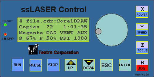 The ssLASER control panel operates on a RS-485 network with the ssLASER
application which is running from flash memory in the ss4544 motion
control system. It is connected to the ss4544 via an RJ-11
4 wire cable which supplies the power and the communication.
At boot up when power is applied, the panel will first display the ss4544
serial number and hardware version number for a few seconds. This message
will then be replaced with the Operation
Display . The display on the panel is a backlit LCD with
four lines of 20 characters each. There is an onboard digital temperature
sensor which is used to temperature compensate the LCD for automatic contrast
control. There are also two LED indicators for job status indication.
A beeper is available for audio signaling. Eleven keys are available
for control, along with an encoder knob. The panel also has a connector
that provides high current control outputs for GAS assist, VENTING,
and an AUXILIARY function. An emergency stop input connector
is also provided. The program that gives the panel its operational
characteristics is part of the ssLASER firmware stored in the ss4544 system.
TABLE OF CONTENTS
1.0 PANEL OPERATION
1.1 OPERATIONAL
CONTROL
1.2 BUFFER
MANAGEMENT
1.3 PARAMETER
ADJUSTMENT
1.3.1
JOG
1.3.2
POWER
1.3.3 SPEED
1.3.4 FOCUS
2.0 MENU SYSTEM
2.1
MAIN MENU
2.2
OPERATION DISPLAY
2.3 PEN
SETTINGS
2.3.1 SETTING
2.3.2 MORE
2.4 BUFFER
CONTROL
2.4.1 INSERT END OF FILE
2.4.2 DELETE THE FILE
2.5 SETUP
2.5.1
TICKLE
2.5.2
CONFIGURATION
2.5.2.1
PORTS
2.5.2.2 LOAD DEFAULTS
2.5.3 DIAGNOSTICS
2.5.3.1 MEMORY TEST
2.5.4 RETAIN SETTINGS
1.0 PANEL OPERATION
After the system is powered up,
the panel will come up in the Operation Display Menu with the ssLASER
in a state ready to accept files from a computer over the RS232 interface.
The state of readiness is indicated by the Ready
lamp on the panel. There are three tasks going
on at the same time that are under control of the panel, Operational,
Buffer Management, and Parameter adjustments. Overviews of
these tasks are described in the following sections.
Since the system multitasks, even while
the Engraver is in operation, you can still move around the Menu
System and execute certain functions. Generally while engraving
you would remain in the Operational Display Menu.
1.1 OPERATIONAL CONTROL
Operational Control
is accomplished using the control button functions on the panel with
a Blue background, and the ADJUST knob or alternatively the UP and
DOWN buttons. These are RUN, PAUSE, STOP, POWER, SPEED, FOCUS, and
the ADJUST knob.. The indicators READY and LASER
along with the display and the audio BEEPER
give operator feedback. Normally the display will be
left in the Operation Display mode while running
the system. The buttons function as follows:
1.1.1 RUN BUTTON
When this button is pushed, the currently
selected file will be output to the laser engraver if the system
is currently idle and not doing diagnostics, and all safety Interlocks
are closed. If the system is currently paused, the job will continue
from it's interruption. If the conditions were true and the output to the
laser engraver is started, the Ready
display will turn on solid. If there is no file selected, the next
file that is output from the connected computer will immediately start
Lasing with the first commands received. A job may be started, even
though the file has not been completely received from the connected computer
system.
1.1.2 INTERLOCK
The Safety interlock is a protection
circuit which when broken disarms the laser so as to avoid operator
injury. Any time the interlock is broken the motion system is also disabled,
and an alarm is indicated by the Laser indicator blinking along with a
click from the beeper. If the interlock is broken while a Job
is running an emergency stop will be created , causing the laser to be
instantly shut off and the motion system to stop as rapidly as possible,
and then turn off all of the motors. The LASER indicator will
then blink about 2 times per second, with an accompanying click from the
beeper. The Ready indicator will also be blinking. Pushing
the Stop button while in this state will terminate the job and ther Ready
indicator will turn off. Pushing it a second time will cause the
motors to be turned back on, the laser light will quit blinking, and the
system will be homed.
1.1.3 GREEN READY INDICATOR
The Ready indicator is lit continually
when the ssLASER system is executing a job file, or if just started
up is waiting to output a file as soon as reception of the job file begins.
It can be put in this mode by pushing the Run
button after power up, and the first file that is received will be immediately
output to the Laser engraver as it is received. If the indicator
is blinking it means the engraver system's currently selected job
is running but paused or about to pause. The Ready indicator
will be extinguished if during the idle or paused state when the indicator
is blinking, the Stop button is pressed causing
the currently selected job to be terminated. The Ready indicator
will also blink three timees at the end of a job along with the Laser indicator
and the Beeper.
1.1.4 RED LASER INDICATOR
The Laser indicator is lit while
a job is running. It will blink about 2 times per second any time
the Interlock is broken.. If the Interlock
is broken while a job is running, the laser will be forced off, and
the indicator will continuously blink and the beeper will click.
It will continue in this mode even if the interlock is restored, until
the Stop button is pressed once causing the
currently selected job to be terminated, and then a second time to rehome
the system. This indicator will also blink three times at the completion
of a job along with the Ready indicator and the Beeper.
1.1.5 PAUSE BUTTON
If a job is currently running,
and the pause button is hit the Ready indicator will
change to a blinking state. The job will then be interrupted as soon
as the current motion vector in progress is completed, at which time the
Laser indicator will turn off. The the lens assembly will then remain
at that point.. If while the job is paused, each time the Pause button
is hit, the lens assembly will be moved either to the view position or
back to the paused position. If the job is currently paused and you are
not in the Jog menu and the Run button is hit
the carriage will move away from its current position and continue
the job from where it was interrupted and the Ready
indicator will turn back on solid.
If there is no job running, clicking
the pause button will cause the lens assembly to be moved alternately between
the view position and the current work zero positiion.
1.1.6 STOP BUTTON
If a job is currently running the STOP
button will have no effect.
If a job is currently paused, hitting
the STOP button will terminate the job. It will not affect the buffer
contents. The Ready indicator will be turned
off.
If no job is running or paused, hitting the
STOP button will home the system. It will not affect the buffer contents.
1.1.7 ADJUSTMENT KNOB
The adjustment knob is multi-purpose
and in most cases may be used in place of the UP and DOWN buttons.
Turning it clockwise is equivalent to the UP key repeatedly pushed.
Turning it counter clockwise is equivalent to the DOWN key repeatedly pushed.
1.1.8 BEEPER
The Beeper is a 4 kHz piezoelectric
audio transducer. At the completion of a job, the
carriage assembly is returned to the View position, and the
Beeper is sounded with a group three of beeps. It is also used to
click while an emergency stop condition has been set.
1.1.9 VENTING
The VENT signal from the panel may be used to turn
on an exhaust system for the Laser Engraver. Whenever a job is started
the VENT signal turns on, and 10 seconds after the job is finished, the
VENT signal is turned off, giving enough time to exhaust residual smoke
and gasses left at the completion of the job.
1.2 BUFFER MANAGEMENT
The Buffer memory is used to buffer
incoming plot data while the Engraver is running or not as long as it is
online. The first job received is given the number 1 as its job number.
Each subsequent job received will be assigned the next number in sequence.
Once the job has been received completely and stored in the buffer, it
may be selected to run later any number of times. Since there is
only so much memory available, at some point you will have a decision as
to delete a job or jobs to make room for another job. A deleted job's
number will disappear from the Job list. New jobs downloaded will
keep getting higher numbers. To manage the buffer, select Buffer
Control from the main menu.
1.3 PARAMETER ADJUSTMENT
Certain parameter may be adjusted directly
by pushing dedicated buttons on the control panel. Other parameters
to be adjusted must be accessed through the menu system.
1.3.1 JOG BUTTON
Hitting the JOG button will only have
an effect if the Lasing operation is Paused or Stopped. It
will switch the system into Jog mode and bring up the Jog Menu. While in
the Jog Menu you are able to move the Lens assembly around the engraving
table, and set new zero points for the Jobs being run. While
in the Jog mode, all of the operational control
functions are no longer in effect (blue background).
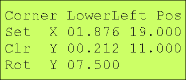 The buttons along
the right side of the panel marked X,Y and Z may be used to select
which Axis is to be jogged, and what jog increment is to be used.
Z is a special case for the ssLASER application which will bring up the
Focus
Menu. When for example the X button is hit, a blinking cursor
will appear over the tenths digit of the X position display. Once
the X position has been selected, repeated hitting of the X Jog Button
will move the cursor through the hundredths digit, then the thousandths
digit, then back to the tenths digit. While one of these digits
is highlighted by the blinking cursor, the UP and DOWN keys may be used
or the ADJUSTMENT Knob may be turned
clockwise or counter clockwise. Turning clockwise or hitting the
UP key will increment the position by the significance of the selected
digit, and counter clockwise or the DOWN key will decrement the position.
The standard adjustment knob has 32 pulses per revolution. Any of
the system axes may be adjusted in the same manner. If either the
UP or DOWN key is held down more than 0.5 second, the key push will automatically
repeat at a rate of about 10 pushes per second. Hitting either the
ESC or ENTER key will turn off the jog function and move the
cursor over to the SET selection in the Jog menu.
While in the JOG mode, the PAUSE
key is still active. You can use it to rapidly move between the WORK
ZERO position, or the VIEW position. The STOP
key is also active. You can use it to HOME the system with a single
keypush. It may also be used for a quick way to set work zero on
flying optic systems if the operator has access to the carriage assembly.
If the STOP key is held down for a couple of seconds, the X and Y motors
will be temporairly turned off. The carriage may then be manually
moved to the work zero positiion. Click the ENTER key while the cursor
is at the SET position in the JOG menu. The system will then be homed,
but it will remember the position that you manually set the carriage to
and load that into the WORK ZERO POSITION.
After making adjustments to the motion system position
using the Jog function, the resulting position may be used to set
a new zero reference point for the Jobs being run using the SET selection.
Other selections may also be made.
The selection is made using the panel UP key or DOWN key to move
the blinking cursor to one of the four selections. If the SEL
key is then hit, the selected function is executed. If the
ESC key is hit the jog menu is exited.
1.3.1.1 CORNER SELECTION
For most applications data is output in a
standard cartesian coordinate system, with the LowerLeft corner
being x0,y0 and positive x increasing to the right and positive y increasing
to the top of the drawing. Some Windows programs use the UpperLeft
corner
as the x0,y0 point with positive x increasing to the right while positive
y increases down from the upper left corner. This is because screen
references in Microsoft software were set up this way. When using
any of our software such as the ssLASER printer driver, this should be
always set to LowerLeft.
1.3.1.2 SET WORK ZERO POSITION
This is the normal and most common use of the JOG
function. If you click on this menu item, the current x,y position
of the Lens assembly is set as the x0,y0 reference point for your job.
1.3.1.3 CLR CLEAR WORK ZERO
Making this selection will set your work x0,y0 reference
back to the CORNER you have selected.
1.3.1.4 ROT SET ROTARY Y AXIS POSITIION
This allows you to position your Y axis over the
centerline of a Rotary Fixture if you are going to use that feature.
If a fixture is mounted with the R-axis motor plugged in, the y-axis
will automatically move to this saved position when engraving, and all
y-axis data will be wrapped about the rotary object.
Back to Table of Contents
1.3.2 POWER BUTTON
Pushing the POWER button will cause the Operation
Display menu to be selected and the cursor to be moved to the power setting
P on the bottom line. The power may be adjusted using the UP and
DOWN keys or using the ADJUST knob. The power setting may be adjusted
at any time, even while a job is running. If the power has been originally
set by software override from the ssLASER windows driver, the adjustment
of the power while the job is running will also be stored in the job file
in the buffer, so if the job is repeated it will use your adjusted power
levels.
1.3.3 SPEED BUTTON
Pushing the SPEED button will cause the Operation
Display menu to be selected and the cursor to be moved to the speed setting
S on the bottom line. The speed may be adjusted using the UP and
DOWN keys or using the ADJUST knob.
The speed setting may be adjusted at any time, even while a job is running.
Warning! Changing the speed currently will cause any lag
compensation for rastered images to become invalid. So for raster
adjustments you should only use power. For cutting it should
be fine. If the speed was set by software override from the ssLASER
windows driver, the adjustment of the speed while the job is running will
also be stored in the job file in the buffer, so if the job is repeated
it will use your adjusted speed levels.
1.3.4 FOCUS BUTTON
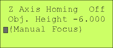
Pushing the FOCUS button brings up this menu
which allows you to adjust the relative position of the focusing lens to
the work.
MENU SYSTEM
The menu system is controlled by the
four buttons on the panel highlighted in blue/green, UP, DOWN, SEL, and
ESC. The ESC key is used to escape or back out of a menu or variable
adjustment. If the ESC key is hit repeatedly, you will eventually
get to the top or Main menu. The UP and DOWN
keys are used to move the menu selection cursor around the menu,
and adjust variables up or down. The ADJUSTMENT knob may also
be used interchangeably with the UP and DOWN keys. The SEL
or select key (ENTER on a PC keyboard) is used to select and cause execution
of the menu item indicated by the highlight or cursor.
2.1 MAIN MENU
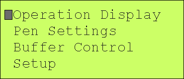 The Main Menu can be reached from any menu by continually hitting
the ESC key, which backs you up one menu level for each push of the
ESC key. From the Main Menu you can go to one of the following menus:
OPERATIONS DISPLAY
PEN SETTINGS
BUFFER CONTROL
SETUP
Back to Table of Contents
2.0 OPERATION DISPLAY
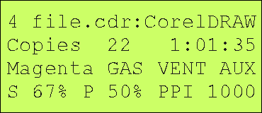 The OPERATION
menu is automatically selected on power up initialization of the
system. Otherwise it is accessed through the menu
system from the MAIN menu. Repeatedly hitting ESC will
always back you up through the menu tree and you will eventually
end up at the MAIN menu. When a job is running or paused
and the operation display has been selected, the display will
be basically as shown here. If the system is idle, the
cursor will be in the upper left corner of the display on the
first line which is the file selection. When in this
state, you may select a different file with the ADJUSTMENT knob or
use the UP or DOWN keys . The number on the line is the file number
in the local buffer memory. The name following is the job file descriptor.
The next line shows the number of Copies
run of the current job followed by a time descriptor.
The first time a file is run, the time descriptor shows the
current elapsed time of the job as it is being run. During
any repeat of the job, the time descriptor will be counting down,
showing how much time remains to finish the job.
The final two lines of the display show the current pen selection
information. The first item on the third line shows the pen identifier
or layer color. This is followed by flags for GAS, VENT, and AUX
which are only visible if that particular function is set on. The
bottom line has first the current SPEED which is indicated by the letter
S followed by the % of full speed. The second parameter is the laser
power indicated by the letter P followed by the % of full power.
The last item is the setting for pulses per inch indicated by PPI followed
by the number.
The power may be adjusted at any time by hitting the POWER
button. This will cause a blinking cursor to appear at the P on the
display. The power may then be adjusted with the ADJUST knob, or
with the UP or DOWN keys. Hitting any other keys will take you out
of that function. In the same manner you may adjust the speed by
hitting the SPEED button. A note of warning here, if you are doing
raster engraving and you have lag compensation, the compensation is currently
done in the Windows ssLASER driver, so adjusting the speed will screw up
the compensation. A future revision of the ssLASER application will
fix this by moving the compensation into the ss4544 firmware.
Back to Table of Contents
3.0 PEN SETTINGS
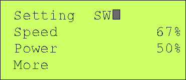 If you SELect the Pen Setting the cursor will move over to just past
the pen number where you can select one of the eight pen settings or the
SW pen setting which is the default. When you do this selection the menu
will change to the SETTING mode which will show you
the Resolution for that pen as well as its Speed and Power setting.
For each selected pen you may adjust any of it's parameters. On this
menu you may only adjust Speed or Power for the pen. To adjust any
other parameters you will have to Click on MORE which
will bring up another menu.
Back to Table of Contents
3.1 SETTING
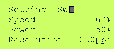 Appears only
while selecting a Pen.
Back to Table of Contents
3.2 MORE
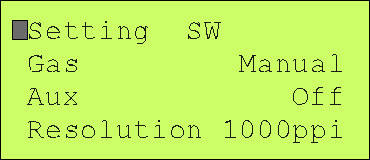 This menu allows you to change the other pen parameters. The GAS
parameter controls the output signal on the panel which may be used to
turn on a valve for gas assist to the laser. The AUX function is
similar to the GAS parameter and may be used for any other function desired
to be associated with a pen. The third function controls the
resolution for firing of the Laser and may be set up to a maximum
of 1000 pulses per inch.
Back to Table of Contents
4.0 BUFFER CONTROL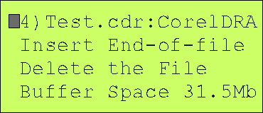
The Buffer control menu is used to manage the job data stored
in the large memory buffer. The last line of this menu shows
the amount of buffer space remaining for jobs. The cursor starts
out on the first line which shows the currently selected job in the
buffer by its number and description from the job file. If
this is selected, the UP and DOWN or ADJUST
knob may be used to scroll through the buffer to see what is in it.
Once the correct file has been located, hit the ESC key to get back
to the menu selections. To delete the job file, move the cursor
to Delete the File and press the SEL key. This will take you to another
Delete
the File menu that asks if you are sure giving you another chance
if pushing the button was a mistake. Once a file is deleted, you
will have to reload it again from your computer if you want to re-run the
job. Also since the buffer memory is volatile if power is turned
off, all of the files will be lost.
Back to Table of Content
4.1 INSERT END OF FILE
 Used to manually
insert an EOF mark in the buffer. This feature is necessary for files that
are sent to the ssLASER application in the ss4544 that come from programs
not compatible with the ssLASER printer driver.
Back to Table of Contents
4.2 DELETE THE FILE
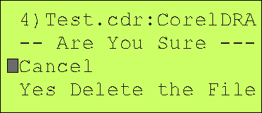 Used to delete
a job in the buffer.
Back to Table of Contents
5.0 SETUP 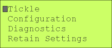
The SETUP menu is used to access primarily maintenance
functions and would not normally be accessed by a machine operator.
These functions include the following menu items:
TICKLE
CONFIGURATION
DIAGNOSTICS
RETAIN SETTINGS
Back to Table of Contents
5.1 TICKLE
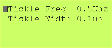 Adjustments
for a CO2 Laser
Back to Table of Contents
5.2 CONFIGURATION
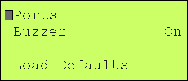
Back to Table of Contents
5.2.1 PORT SETTINGS
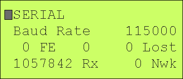
Back to Table of Contents
5.2.2 MOTION SETTINGS
Back to Table of Contents
5.2.2.1 JOG, ZERO SET
5.2.3 DEFAULTS
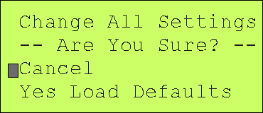 Used to
reload default parameter settings.
Back to Table of Contents
5.3 DIAGNOSTICS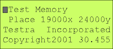
The Diagnostics menu allows you to test the buffer memory
in the ss4544 system that is used to buffer jobs downloaded from your PC
application or from the ssLASER driver. The size of the memory installed
is shown in the bottom left corner of the menu.
To run the memory diagnostics, you will
first have to either terminate or let finish any job that is running.
The running of the memory test will destroy any jobs you have downloaded,
so they will have to be reloaded after the memory test is run. With
the cursor on line one in front of Memory Test push the SEL key.
This will bring up the MEMORY test menu.
To run the Motion Test you will also have to terminate
or let finish any job that is running. Then move the cursor down
in front of the Motion test selection and press SEL
Back to Table of Contents
5.3.1 MEMORY TEST
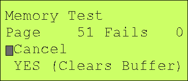 The memory test may be Canceled at any time by hitting the SEL key while
the cursor is positioned in front of Cancel. Otherwise position the
cursor in front of Yes and hit the SEL key. This will start up the
memory test. The memory test will run continuously until you terminate
the test by doing a Cancel. At that point you can leave this menu
by hitting ESC.
The memory is broken up into pages of 65535 bytes.
As each page is tested the page number displayed will be updated.
Any failures encountered will be added to the Fails counter.
Back to Table of Contents
5.4 RETAIN SETTINGS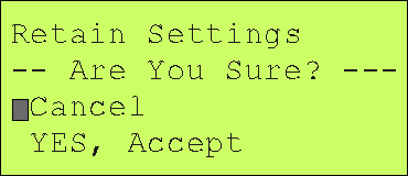
You may either cancel or accept the settings.
Updated July 28, 2001
GO TO HOME PAGE
If you have comments or suggestions, email us
at support@testra.com
Testra Corporation 1201 N. Stadem Drive Tempe, AZ
85281 Ph. 480-560-6141 Fax: 480-907-2876
 SS4544 SyncroStep Motion Control System