 SS4544
SyncroStep
Motion Control System
Application Note 108 - Step Motor Compensation
Revised
5/27/03
Testra Corporation 1201 N. Stadem Drive Tempe, AZ 85281 Ph:(480)560-6141
Fax:(480)907-2876
GO TO HOME PAGE
Microstep Response in a Step Motor
 Step motors when micro stepped with a sine wave excitation generally do
no give a linear response for a variety of mechanical and electrical reasons.
The pole shapes may not be ideal, and the magnetic path is affected by
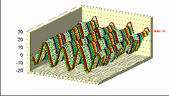
saturation. The following graph shows the error response of very
good step motor when driven with a sine wave.
The vertical scale represents error in microsteps of 1/256th of
a step. The horizontal scale represents four steps across one pole of the
motor, while the depth starting at the back represents which of the 50
poles on the motor. The very first pole graph is offset by the hysteresis
of the motor. The test setup was done with a Gurly 36,000 count per revolution
high resolution encoder, with the motor driven with our ss4544 motor control
system.
Creating the Compensation Tables
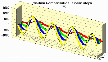
 The motor is actually analyzed at four different current points that span
the motors normal operating range. The analysis creates a phase offset
that can be used for correction. This phase offset is the average
across all 50 poles of the motor. The graph is set up with the phase
compensation on the vertical axis in 1/16384th of a step. The horizontal
axis represents one pole transition or four steps. The depth axis
represents four different current levels. Blue is 100% of the rated
motor current, while Yellow is 120% of rated current, Green 80% or rated
current, and Red 60% of rated current. You can easily see from the
graphs that the non linearity increases with increasing current. This is
due to magnetic saturation in the motor.
Microstep Response after Compensation
 The
compensation tables thus created are then loaded into the ss4544 motion
control system which interprets them to create the appropriate drive current
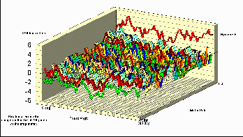
waveform. The following graph shows the motor microstep response
with the new current drive waveform. Note that the scale on this graph
is 5 times finer than the first graph showing the uncompensated motor response.
This improvement in positioning accuracy is even more dramatic on other
step motors that do not have as good performance as the one analyzed here.
Note: We also have a method of elimination of the hysteresis of the
motor in positioning applications where extreme precision is needed.
This is standard in the ss4544
motor control system. In the ss483
driver it would be a custom version for OEM use.
GO TO HOME PAGE
If you have comments or suggestions, email us
at support@testra.com
Testra Corporation 1201 N. Stadem Drive Tempe, AZ
85281 Ph. 480-560-6141 Fax: 480-907-2876
 Step motors when micro stepped with a sine wave excitation generally do
no give a linear response for a variety of mechanical and electrical reasons.
The pole shapes may not be ideal, and the magnetic path is affected by
saturation. The following graph shows the error response of very
good step motor when driven with a sine wave.
 SS4544
SyncroStep
Motion Control System

